Date: 2 June 2026

Modern enterprise infrastructure is no longer judged solely by raw compute performance. Today, true sustainability means operational survivability, resilience, predictability, fault tolerance, and the ability to absorb catastrophic hardware or network failures without a single millisecond of business interruption.
For high-load, zero-downtime industries such as FinTech, AdTech, iGaming, SaaS, real-time AI platforms, and media streaming, infrastructure sustainability begins at the silicon level and extends across the entire network topology. This guide breaks down how to engineer an enterprise-grade, active-active, geo-distributed infrastructure from the ground up.
What Sustainable Infrastructure Actually Means?
In enterprise IT, sustainability is often conflated with environmental green initiatives. While energy efficiency (PUE optimization) is critical, structural infrastructure sustainability primarily refers to operational survivability.
A truly sustainable platform must maintain deterministic performance even during simultaneous hardware failures, core switch outages, localized power grid collapses, massive DDoS attacks.
Layer 1: Redundancy Starts Inside the Server
Resilience begins at the physical bare-metal layer. A sustainable architecture operates on an assumption of inevitable hardware failure.
Physical Component Hardening
Every enterprise-grade dedicated server within the fleet must feature:
- Dual Hot-Swappable PSUs: Connected to independent A/B power distribution units (PDUs) fed by separate utility grids or UPS systems.
- ECC Memory (Error-Correcting Code): Utilizing Advanced ECC or memory scrubbing modes to detect and correct multi-bit memory errors, preventing kernel panics and silent data corruption.
- Redundant Cooling Fans: Hot-swappable, N+1 or N+2 fan configurations capable of ramping up RPMs dynamically if a single fan fails.
Storage Redundancy & IOPS Predictability
To eliminate storage as a failure domain while maintaining maximum IOPS under production workloads, infrastructures rely on strict physical and logical partitioning:
- Local NVMe Arrays: Configured via hardware or robust software RAID (such as RAID-10 or RAID-1) to allow instant drive rebuilds without degrading application read/write limits.
- Distributed Storage Nodes: Deploying NVMe-over-Fabrics (NVMe-oF) or Ceph clusters to decouple compute from stateful storage, allowing seamless node failures.

Layer 2: Eliminating Single Points of Failure (SPOFs) in the Rack
A perfectly redundant server will still fail if its host rack contains architectural bottlenecks. Standard enterprise topology dictates an entirely isolated, dual-pathed architecture at the rack level.
|
Component |
Minimum Resilient Specification |
Failure Mode Mitigated |
|
Top-of-Rack (ToR) Switches |
Dual Active-Active Switches running MC-LAG or EVPN-multihoming |
Single ASIC failure, OS crash, or firmware update downtime |
|
Network Interfaces |
Dual-port NICs cross-connected to separate ToR switches using LACP (802.3ad) |
Transceiver failure, fiber patch cable snap |
|
Power Distribution |
Intelligent, networked A/B PDUs drawing from independent UPS systems |
Phase overload, PDU circuit breaker trip |
|
Out-of-Band (OOB) Management |
Dedicated, air-gapped management network (IPMI/iDRAC) via separate switches |
Inability to access nodes during a broadcast storm or control plane failure |
Layer 3: Network Topology and Dual-Ring Dark Fiber Architecture
The network layer is traditionally where infrastructure fragility peaks. Standard primary/backup routing models introduce unpredictable failover convergence times. High-load enterprise platforms require active-active network topologies with deterministic latency.
The Physics of Sub-1ms RTT
To achieve a Round-Trip Time (RTT) below 1 millisecond, the physical distance between data centers is strictly limited by the speed of light in fiber optic cables.
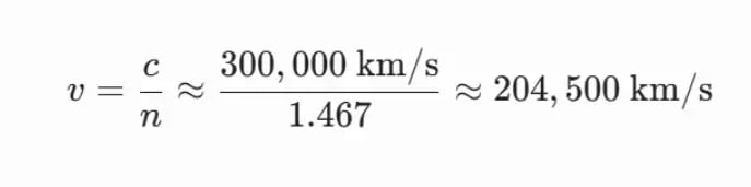
The speed of light in a vacuum is approximately 300,000,000 meters per second. However, inside a standard silica fiber optic cable, light travels slower due to the refractive index of the fiber core (approximately 1.467).
The propagation speed inside the fiber is calculated as:
v = c / n
Where:
- v = propagation speed in the fiber
- c = speed of light in a vacuum
- n = refractive index of the fiber
This results in an effective signal propagation speed of approximately:
204,000 kilometers per second
Since RTT measures the full round trip, the theoretical maximum one-way distance for sub-1ms RTT is roughly:
100 kilometers
In real-world deployments, the achievable distance is even shorter because of:
- fiber routing inefficiencies,
- optical switching delays,
- DWDM equipment latency,
- router and switch processing,
- and physical cable path deviations.
As a result, enterprise infrastructures targeting consistent RTT below 1ms typically place interconnected data centers within approximately 50–80 kilometers of each other and connect them using dedicated dual-ring dark fiber topology.
This architecture enables:
- synchronous storage replication,
- active-active database clusters,
- ultra-fast failover,
- live VM migration,
- and geographically distributed high-availability environments without significant latency penalties.
This translates to roughly 1 ms of RTT for every 100 km of physical fiber run (since the signal must travel to the destination and back). Therefore, to guarantee a sub-1ms RTT (including a buffer for network switch serialization and encapsulation delays), data centers must be located within a 40–75 km fiber routing radius.

Dual-Ring Dark Fiber & DWDM
By leasing unlit (dark) fiber paths, enterprises construct dedicated, private dual-ring topologies. Using Dense Wavelength Division Multiplexing (DWDM), a single pair of optical fibers is multiplexed into dozens of independent wavelengths, providing massive multi-terabit throughput without public internet routing instability.
If an external construction incident cuts Route 1, optical transponders automatically reroute traffic via Route 2 using protocols like APS (Automatic Protection Switching) or G.8032 ERPS (Ethernet Ring Protection Switching). This convergence happens at the hardware layer in less than 50 milliseconds, keeping the network degradation completely unnoticeable to the application layer.
Layer 4: Geo-Distributed Storage Replication & The Split-Brain Dilemma
When operating multiple data centers within a sub-1ms RTT envelope, selecting the correct storage replication strategy determines whether data remains consistent during an isolation event.
Synchronous vs. Asynchronous Replication
- Synchronous Replication (RPO = 0): Every write operation must be written to local storage and transmitted, received, and committed to the remote data center's storage before an acknowledgment (ACK) is sent back to the client application.
- Why Sub-1ms RTT is mandatory: If your inter-DC latency spikes to 20ms, your database write performance drops from thousands of transactions per second to a maximum of 50 per single thread. Sub-1ms RTT allows synchronous replication to occur with negligible application overhead.
- Asynchronous Replication (RPO > 0): Writes are committed locally and immediately acknowledged. A background process batches and replicates changes to the remote facility. While this supports long-distance replication, an abrupt primary data center failure guarantees data loss equal to the replication lag.
Mitigating Split-Brain Scenarios
In an active-active multi-data-center setup, a sudden loss of network connectivity between sites can cause both locations to assume the other is dead. Both sides will attempt to write to the same database tables simultaneously, corrupting the global state.
⚠️ Engineering Rule: Quorum Require Three Points
To prevent split-brain errors, true high-availability architectures require a third, independent tie-breaker location to establish a quorum.
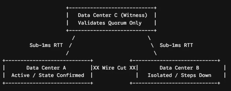
By placing a lightweight witness node or an odd-numbered cluster node in a third physical zone, distributed clustering engines (such as Etcd, Consul, or Galera) can execute an automated vote. If Data Center A can talk to the Witness but Data Center B is completely cut off, Data Center B will gracefully step down, preserving data integrity.
Layer 5: Distributed Compute Architecture with K8s and Anycast
With low-latency networking and consistent storage in place, the compute layer can run across data centers in a unified, elastic fabric.
Using Kubernetes (K8s) multi-cluster topologies or cross-site OpenStack control planes, workloads are scheduled dynamically based on resource availability. If a cluster node in Facility A degrades, the control plane orchestrates a seamless reschedule of pods onto Facility B.
Global Traffic Steering via BGP Anycast
To route users to the healthiest and closest data center, modern infrastructures move away from standard DNS round-robin routing (which suffers from aggressive ISP caching and slow convergence). Instead, they deploy BGP (Border Gateway Protocol) Anycast.
With Anycast, both Data Center A and Data Center B advertise the same IP address space to upstream Tier-1 internet transit providers.
- Under normal conditions, users are naturally routed to the topologically closest data center.
- If Data Center A drops completely offline, the local BGP daemon drops the route advertisement. Within seconds, the global internet routing table converges, and all incoming user traffic is automatically directed to Data Center B without changing a single client-side DNS record.

Layer 6: Backup vs. High Availability (HA)
A critical architectural pitfall is confusing high availability with comprehensive backup strategies. HA keeps your services online during hardware failures; backups protect your business against data destruction.
- The HA Reality: If an application bug runs a malicious DROP DATABASE command, synchronous replication will instantly delete that database across all data centers simultaneously in under 1 millisecond.
- The Sustainable Solution: Implement an independent, decoupled backup architecture utilizing immutable storage (WORM - Write Once, Read Many). Backups must be cryptographically signed, versioned, entirely isolated from the main production network plane, and continuously audited using automated restoration tests to guarantee a reliable Recovery Time Objective (RTO).
Layer 7: Security via Physical Isolation and Zero Trust Hardware
True structural sustainability requires complete control over the security perimeter. The hidden risk of multi-tenant public cloud hyperscalers is the lack of underlying hardware predictability and isolation.
The Vulnerabilities of Shared Public Clouds
- Noisy Neighbors: Neighboring virtual machines on the same bare-metal host can consume shared CPU cache or hypervisor bus bandwidth, causing unpredictable latency spikes.
- Side-Channel Attack Surfaces: Shared infrastructure exposes systems to hardware-level vulnerabilities such as Spectre, Meltdown, or hypervisor breakout exploits.
- Data Sovereignty and Compliance: In shared public clouds, verifying exactly which physical silicon or disk sector holds sensitive customer data is difficult, complicating strict compliance validations (like PCI DSS or GDPR).
Implementing Hardware-Layer Zero Trust
By migrating high-load production workloads to dedicated, physically isolated private infrastructure, organizations can enforce Zero Trust starting directly at the hardware layer:

- Hardware Root of Trust: Utilizing cryptographic coprocessors like TPM 2.0 (Trusted Platform Module) to verify the integrity of the bootloader, kernel, and system software before allowing the server onto the private production network fabric.
- Hardware-Level Segmentation: Isolating distinct business microservices onto separate physical servers or dedicated, non-shared hypervisor networks via private VLANs (QinQ) and VXLAN overlays.
- Physical Layer Encryption: Leveraging inline NVMe cryptographic engines to ensure data is encrypted at rest directly on the drive controllers, completely decoupled from central host CPU overhead.
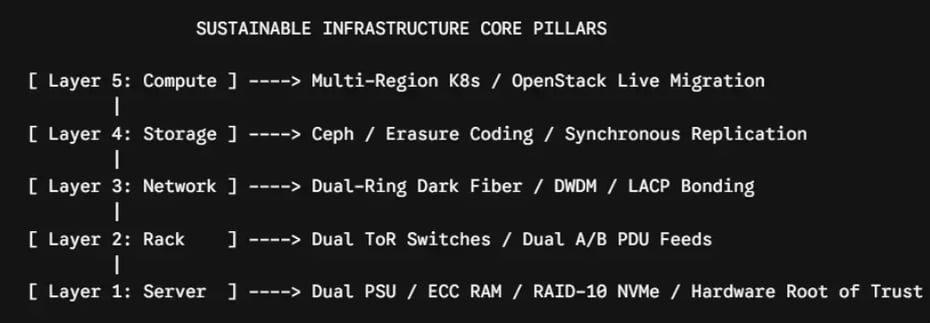
Blueprint: The Sustainable Enterprise Infrastructure Stack
A comprehensive summary of the architecture required to build a resilient, predictable, high-performance platform:

The Move Toward Infrastructure Predictability
As digital systems mature, enterprise organizations running highly predictable, continuous workloads are actively shifting away from standard multi-tenant cloud hyperscalers. The unpredictable nature of shared resource contention, volatile data egress fees, and lack of control over the physical network topology introduce unnecessary operational risks.
Building a sustainable, dedicated infrastructure using private single-tenant compute nodes, distributed storage fabrics, and redundant local networks interconnected by low-latency dark fiber loops puts full control back into the hands of enterprise architects.
By prioritizing structural redundancy at every single layer, you build a platform designed to withstand individual hardware and network failures without degrading customer experience.